IMU Sensors Explained: Accelerometers, Gyroscopes, and Sensor Fusion
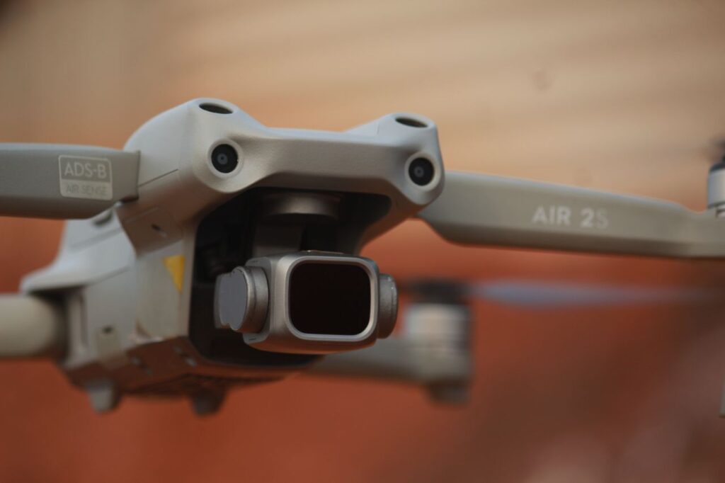
An IMU (Inertial Measurement Unit) is a sensor package that measures a body's specific force, angular rate, and often the surrounding magnetic field, using a combination of accelerometers, gyroscopes, and sometimes magnetometers. By fusing the outputs of these sensors, an IMU lets a drone, robot, headset, or phone estimate its orientation and motion without any external reference. In this guide you'll learn what each sensor inside an IMU actually measures, how MEMS technology makes them tiny and cheap, why raw IMU data drifts and needs sensor fusion, and which IMU modules make sense for maker projects.
- What Is an IMU Sensor?
- The Accelerometer: Measuring Specific Force
- The Gyroscope: Measuring Angular Rate
- The Magnetometer: An Absolute Heading Reference
- How MEMS Technology Makes IMUs Tiny and Cheap
- Drift, Bias, and Noise: The Errors Every IMU Has
- Why IMUs Need Sensor Fusion
- Popular IMUs for Makers: MPU-6050, BNO055, ICM-20948
- Where IMUs Are Used: Drones, Wearables, Robots, VR, Navigation
- Frequently Asked Questions About IMU Sensors
What Is an IMU Sensor?
An inertial measurement unit is not a single sensor but a cluster of them, mounted on one chip or board and sampled together. The classic configuration measures motion along and around three orthogonal axes (X, Y, Z), which is why IMU specs talk about degrees of freedom (DoF):
- 6DoF IMU: 3-axis accelerometer + 3-axis gyroscope. Enough for orientation relative to gravity and short-term motion tracking, but it cannot tell magnetic north.
- 9DoF IMU: adds a 3-axis magnetometer, giving an absolute heading reference (a compass). Often marketed as MARG sensors (Magnetic, Angular Rate, Gravity).
- 10DoF boards: add a barometric pressure sensor for altitude — common on flight controllers, though strictly speaking the barometer isn't an inertial sensor.
The IMU's job is to answer two questions continuously: which way am I pointing? (attitude: roll, pitch, yaw) and how am I moving? (acceleration and angular velocity). Everything from a quadcopter's flight controller to the screen rotation on your phone depends on those answers being fast and reliable.
IMUs are the workhorse of inertial navigation, but they are almost never used alone. As we'll see below, each internal sensor has characteristic errors that the others help correct — the textbook case of sensor fusion.
The Accelerometer: Measuring Specific Force
An accelerometer measures specific force — the acceleration it experiences relative to free fall — in meters per second squared or in g (1 g ≈ 9.81 m/s²). Two consequences of that definition surprise beginners:
- An accelerometer sitting still on a table reads +1 g upward, because the table pushes against gravity. That constant gravity vector is precisely what makes accelerometers useful for tilt sensing: by looking at how the 1 g vector projects onto the X, Y, and Z axes, you can compute roll and pitch when the device is not accelerating.
- An accelerometer in free fall reads zero, even though it is clearly accelerating toward the ground.
The weakness: an accelerometer cannot distinguish gravity from linear acceleration. Brake hard in a car and a naive tilt calculation will swear the vehicle is pitching nose-down. Accelerometer-only orientation is therefore accurate on average but very noisy and easily fooled in the short term.
The Gyroscope: Measuring Angular Rate
A gyroscope measures angular velocity — how fast the device is rotating around each axis, in degrees or radians per second. Note that a MEMS gyro does not measure orientation directly; you get orientation by integrating the angular rate over time.
Gyroscopes are the mirror image of accelerometers: superb in the short term (smooth, fast, immune to vibration and linear acceleration) but unreliable in the long term. Every gyro reading contains a small bias error, and integration accumulates that error second after second. This is the infamous gyro drift: leave a gyro-only orientation estimate running and it can wander several degrees per minute even while the sensor sits perfectly still.
The Magnetometer: An Absolute Heading Reference
A magnetometer measures the local magnetic field along three axes. Since the Earth's field points (roughly) toward magnetic north, it works as a digital compass and provides the one thing an accelerometer + gyroscope pair cannot: an absolute yaw reference. Roll and pitch drift can be corrected against gravity, but yaw drift can only be corrected against magnetic north (or GPS heading, or vision).
Magnetometers come with their own headaches: they are easily disturbed by motors, speakers, steel structures, and current-carrying wires. Calibration distinguishes hard-iron distortion (a constant offset from magnetized material on the device itself) and soft-iron distortion (field warping by nearby ferromagnetic material). Any serious 9DoF project includes a magnetometer calibration routine — the familiar "wave your phone in a figure-eight" dance.
How MEMS Technology Makes IMUs Tiny and Cheap
Aerospace-grade IMUs once used spinning-mass gyros and ring-laser gyroscopes the size of coffee cans. What put an IMU in every phone and hobby drone flight controller is MEMS — Micro-Electro-Mechanical Systems, microscopic mechanical structures etched into silicon alongside the electronics that read them.
- MEMS accelerometer: a microscopic proof mass suspended on silicon springs. Acceleration displaces the mass, changing the capacitance between interleaved comb fingers; the chip converts that capacitance change into a force reading.
- MEMS gyroscope: a mass driven to vibrate at a known frequency. When the chip rotates, the Coriolis effect nudges the vibrating mass sideways, and that tiny orthogonal deflection is proportional to angular rate.
- Magnetometer: usually not mechanical at all — Hall-effect or magnetoresistive elements whose electrical properties change with the ambient field.
MEMS made inertial sensing incredibly cheap, but physics still charges a price: microscopic proof masses are sensitive to temperature, manufacturing tolerances, and vibration, which is exactly where IMU error models come in.
Drift, Bias, and Noise: The Errors Every IMU Has
Understanding IMU errors matters more than memorizing datasheets, because these errors dictate the entire architecture of any project that uses inertial data:
- Bias (offset): the sensor reports a nonzero value when the true value is zero. Part of it is constant and calibratable; part of it wanders slowly with time and temperature (bias instability).
- Noise: random variation on every sample. In gyros it is specified as angle random walk — noise that, once integrated, makes the orientation estimate wander randomly.
- Drift: the cumulative result of integrating bias and noise. Gyro drift corrupts orientation in minutes; double-integrating accelerometer error to get position drifts meters within seconds, which is why IMU-only "dead reckoning" position tracking is essentially unusable without external corrections.
- Scale-factor error and axis misalignment: the sensor gain is slightly off, or the axes are not perfectly orthogonal — both correctable with factory or user calibration.
Here is how the three sensors' strengths and weaknesses interlock:
| Sensor | What it measures | Typical error | Compensated by |
|---|---|---|---|
| Accelerometer | Specific force (linear acceleration + gravity) | High-frequency noise; confuses gravity with linear acceleration | Gyroscope smooths short-term motion; fusion filter weights it only in the long term |
| Gyroscope | Angular velocity (rate of rotation) | Bias → drift accumulates when integrated to orientation | Accelerometer (gravity reference for roll/pitch) and magnetometer (north reference for yaw) |
| Magnetometer | Local magnetic field (heading) | Hard/soft-iron distortion; interference from motors and wiring | Calibration routines; gyroscope rejects sudden magnetic disturbances |
| Barometer (10DoF) | Air pressure (relative altitude) | Weather-induced pressure shifts, slow response | Accelerometer Z-axis for fast altitude changes; GPS altitude |
Why IMUs Need Sensor Fusion
Look at the table above and the pattern is obvious: each sensor's weakness is another sensor's strength. The gyro is trustworthy for seconds but drifts over minutes; the accelerometer and magnetometer are noisy second to second but anchored to physical references (gravity, north) that never drift. A fusion algorithm blends them so the estimate is smooth in the short term and stable in the long term. The three approaches you will meet in practice:
- Complementary filter: the simplest — high-pass the gyro, low-pass the accelerometer, and add them (e.g., 98% integrated gyro + 2% accelerometer angle per update). A few lines of code, runs on any microcontroller, and is surprisingly good for hobby drones and balancing robots.
- Kalman filter (and Extended Kalman Filter): the statistically optimal approach. It maintains an estimate of the state and its uncertainty, predicting with the gyro and correcting with the accelerometer/magnetometer, weighting each source by how much it can currently be trusted. The EKF is the standard in flight controllers (PX4, ArduPilot) and robotics.
- Madgwick and Mahony filters: gradient-descent and PI-feedback orientation filters designed specifically for IMU/MARG data. They deliver near-Kalman accuracy at a fraction of the computational cost, which made Madgwick's open-source AHRS implementation the default choice on Arduino-class hardware.
We compare these filters in depth — including when a complementary filter is genuinely enough and when you need an EKF — in our guide to sensor fusion algorithms. And orientation is only the beginning: full navigation stacks fuse IMU data with GPS, cameras, or ranging sensors, exactly as autonomous vehicles do when combining inertial data with LiDAR and radar.
Popular IMUs for Makers: MPU-6050, BNO055, ICM-20948
Note: we mention specific modules for reference only; this article contains no affiliate links.
Three chips dominate maker projects, each representing a different philosophy:
MPU-6050 (InvenSense/TDK) — the classic budget 6DoF. A 3-axis accelerometer + 3-axis gyro with a Digital Motion Processor, available on GY-521 breakout boards for a couple of dollars. It is officially end-of-life and its onboard fusion is limited, but the documentation, tutorials, and library support are unmatched. Perfect for learning: read raw data over I²C, implement your own complementary filter, and watch drift happen in real time.
BNO055 (Bosch Sensortec) — fusion done for you. A 9DoF system-in-package with a built-in Cortex-M0 that runs the fusion algorithm on the chip and outputs ready-to-use quaternions or Euler angles at 100 Hz. You skip filter tuning and magnetometer math entirely. The trade-offs: higher price, autocalibration that can behave unpredictably, and no access to tune the internal filter. Ideal when orientation is a means to an end — robot arms, head trackers, camera gimbals. Details in the Bosch Sensortec BNO055 documentation.
ICM-20948 (TDK InvenSense) — the modern 9DoF workhorse. The designated successor to the MPU-9250: lower power, better noise specs, 9 axes plus a DMP capable of on-chip fusion. It is the current default on many SparkFun and Adafruit boards and the sensible choice for new intermediate-to-advanced designs where you still want control over the fusion running on your host processor.
A good rule of thumb: MPU-6050 to learn, BNO055 to ship a quick project, ICM-20948 to build something serious. All three speak I²C (most also SPI), so they wire directly to an Arduino, ESP32, or Raspberry Pi — a self-balancing robot or motion tracker built on one of these is a natural companion to the builds in our Raspberry Pi 5 projects guide.
Drones and flight controllers. The IMU is the heart of every flight controller: the attitude loop reads fused IMU orientation hundreds to thousands of times per second to keep the aircraft level. Flight controllers routinely carry redundant IMUs, mounted on vibration-damping foam, because propeller vibration is exactly the kind of high-frequency noise that corrupts MEMS sensors.
Wearables and smartphones. Step counting, sleep tracking, fall detection, gesture recognition, screen rotation, and optical image stabilization all run on the phone's or watch's IMU, with heavily optimized low-power fusion running continuously in the background.
Robotics. Wheeled and legged robots fuse IMU data with wheel odometry to fight wheel slip; balancing robots and drones use it in the control loop itself; SLAM systems use the IMU to predict motion between camera or LiDAR frames (visual-inertial odometry).
VR and AR headsets. Headsets track orientation with IMUs at very high rates because latency above roughly 20 ms between head motion and display update causes motion sickness. Cameras periodically correct the IMU's drift — inside-out tracking is IMU-plus-vision sensor fusion running at full speed on your face.
Inertial navigation. Aircraft, ships, submarines, and missiles carry high-grade IMUs (fiber-optic or ring-laser gyros with far lower bias instability than MEMS) that dead-reckon position when GPS is unavailable or jammed. In cars and smartphones, MEMS IMUs bridge GPS outages in tunnels and urban canyons — another fusion problem, with the Kalman filter again at the center.
For more on how inertial data combines with cameras, LiDAR, radar, and other modalities, browse the rest of our sensor fusion articles.
Frequently Asked Questions About IMU Sensors
What is the difference between an IMU and a gyroscope?
A gyroscope is a single sensor that measures angular velocity (how fast something rotates). An IMU is a package that combines a gyroscope with an accelerometer — and often a magnetometer — and samples them together. Every IMU contains a gyroscope, but a gyroscope alone is not an IMU.
Can an IMU measure position?
Not reliably on its own. Position requires double-integrating acceleration, and any bias or noise error grows quadratically with time — a cheap MEMS IMU accumulates meters of position error within seconds. Practical systems use the IMU for orientation and short-term motion prediction, and fuse it with GPS, cameras, LiDAR, or wheel odometry for position.
What does 6DoF vs 9DoF mean in an IMU?
6DoF means six degrees of freedom: a 3-axis accelerometer plus a 3-axis gyroscope. 9DoF adds a 3-axis magnetometer. The practical difference is yaw: a 6DoF IMU can reference roll and pitch against gravity but its yaw estimate drifts, while a 9DoF IMU can correct yaw against magnetic north — provided the magnetometer is calibrated and away from magnetic interference.
Which IMU is best for beginners?
The MPU-6050 is the best learning platform: extremely cheap, hugely documented, and it forces you to understand raw data and filtering. If you just need reliable orientation with zero fusion math, the Bosch BNO055 outputs ready-made quaternions from its on-chip fusion processor. For new intermediate designs, the ICM-20948 offers the best specs-per-dollar of the three.
Recommended: