Time-of-Flight Sensor Explained: dToF vs iToF, and Real Specs
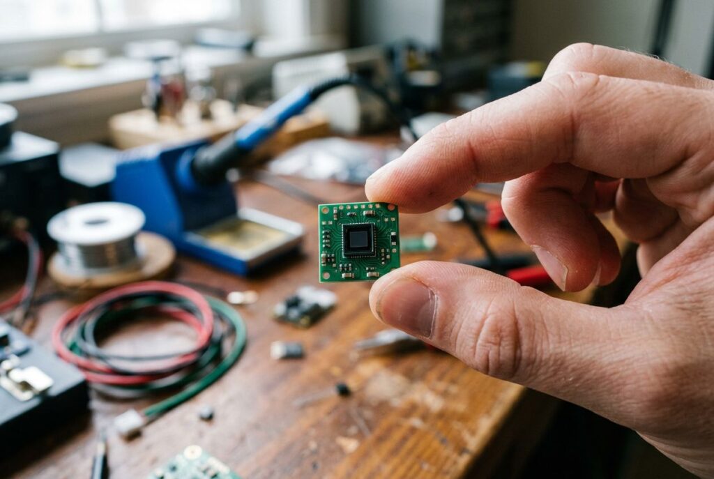
A time-of-flight (ToF) sensor measures distance by timing how long light takes to travel to an object and bounce back, then converts that time into a range using the speed of light. Cheap single-chip ToF modules — most commonly STMicroelectronics' VL53L0X and VL53L1X — put this principle on a board the size of a fingernail, which is why they show up in everything from Arduino robots to smartphone cameras. This guide covers how ToF sensors actually work, the difference between direct and indirect ToF, how the technology relates to LiDAR, which module to pick, and what trips people up when they wire one in for the first time.
How a time-of-flight sensor works
Every ToF sensor follows the same basic recipe: an illumination unit (a laser diode or LED) fires a burst of infrared light at the scene, a detector captures the light that bounces back, and driver electronics convert the round-trip delay into a distance. Because light travels at a fixed, known speed, the math is straightforward: distance equals the speed of light multiplied by the round-trip time, divided by two. An object 2.5 meters away, for example, delays the returning light by about 16.7 nanoseconds — which is why the sensor's timing electronics have to be accurate down to picoseconds to get millimeter-level precision.
A complete ToF sensor is built from four parts working together: the illumination unit, optics (a lens plus an optical band-pass filter tuned to the illumination wavelength, which blocks ambient light), the image or photo sensor that actually times the returning light, and the driver/computation electronics that synchronize the emitter and detector and output a distance reading, typically over I2C, USB, or Ethernet depending on the device.
Direct vs. indirect time-of-flight (dToF vs. iToF)
"Time-of-flight sensor" is an umbrella term that covers two genuinely different measurement techniques, and knowing which one a given module uses explains most of its strengths and limits.
Direct time-of-flight (dToF)
Direct ToF sensors fire a single, very short laser pulse (a few nanoseconds) and measure the actual elapsed time until a detector registers the reflection — the same principle used in flash LiDAR. The small breakout-board sensors covered below use this approach: they pair a VCSEL (vertical-cavity surface-emitting laser) emitter with a SPAD (single-photon avalanche diode) receiving array that can register individual returning photons and timestamp them. The sensor builds a histogram of photon arrival times across many pulses, filters out ambient-light noise, and picks the peak as the true distance. Because it measures absolute travel time rather than light intensity, direct ToF gives distance readings that don't depend much on a target's color or reflectivity.
Indirect time-of-flight (iToF)
Indirect ToF sensors don't time individual pulses. Instead, they modulate a continuous light source — an RF-modulated LED or laser — and measure the phase shift between the outgoing and returning signal at each pixel, then convert that phase shift into distance. This is the technique behind full ToF depth cameras such as the Photonic Mixer Device (PMD) family and the Microsoft Kinect's second-generation sensor (developed from technology Microsoft acquired with Canesta and 3DV Systems). It produces a full depth image per frame rather than a single point reading, which is why it's the basis for gesture-control and 3D-scanning cameras rather than simple rangefinder chips. The trade-off is a "modulo" ambiguity: because the phase measurement repeats every modulation wavelength, a target beyond the camera's unambiguous range can be reported at the wrong distance unless the firmware applies phase-unwrapping.
Is a ToF sensor the same as LiDAR?
The terms overlap enough to cause real confusion. Laser-based time-of-flight cameras are, by definition, part of a broader class of scannerless LiDAR: they capture the entire scene in one laser pulse, instead of building an image point-by-point by sweeping a laser beam the way a scanning LiDAR unit does. So a ToF camera is a type of LiDAR in the strict technical sense — but in everyday usage, "LiDAR" usually refers to scanning systems that produce a dense 3D point cloud (the kind used in autonomous vehicles and drone mapping), while "ToF sensor" more often refers to the small single-point or low-resolution rangefinder chips covered in this guide, like the VL53L0X and VL53L1X. If you're deciding between the two technologies for a project, our LiDAR vs radar comparison covers how scanning LiDAR stacks up against other ranging technologies in more depth.
ToF sensor modules you can actually buy
For makers and embedded projects, "buying a ToF sensor" almost always means buying a breakout board built around one of two ST FlightSense chips. Both are direct-ToF, both talk I2C, and both are small enough to hide inside a 3D-printed enclosure — but they're aimed at different ranges.
VL53L0X — the original, short-range breakout
The VL53L0X uses a narrow infrared laser source and a matching SPAD-based detector to measure distance in a roughly 35-degree cone. In its default mode it reliably covers about 30 mm to 1.2 meters, extending to 1.5–2 meters in "long range" mode against a bright, reflective surface; ranging accuracy runs from roughly 3% to 12% depending on ambient light and the target's surface. It talks over I2C and is the sensor most beginner Arduino and Raspberry Pi tutorials are built around.
Disclosure: this article contains affiliate links. If you buy through them we may earn a small commission at no extra cost to you.
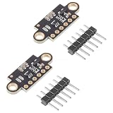
- Note:It is recommended to read the VL53L0X datasheet before using this product
- VL53L0X:A time-of-flight ranging system integrated into a compact module
- Function:VL53L0 is a small self-contained liDAR system,which uses ST's FlightSense technology to measure the time it takes for emitted infrared laser pulses to reach the nearest object and reflect back to the detector
- Working Voltage: 2.8V-5V;Communication method: IIC communication protocol (compatible with 3-5V system)
- Package Includes:2 x VL53L0X Time-of-Flight Ranging Sensors
VL53L1X — longer range with a programmable field of view
The VL53L1X is the newer, longer-range sibling: a 940 nm Class 1 VCSEL laser paired with a 16x16 SPAD receiving array gives it a rated range of about 40 mm to 4 meters at millimeter resolution, over I2C running up to 1 MHz. It offers three distance modes that trade range for ambient-light immunity — short mode tops out around 1.3 m but is largely unaffected by ambient light and can sample at up to 50 Hz, while long mode reaches the full 4 m but is more sensitive to bright ambient conditions and samples at up to 30 Hz. Its field of view is a typical 27 degrees at default settings, and firmware can narrow that down by selecting a smaller Region of Interest (ROI) on the SPAD array — useful for pointing the sensor at a specific target instead of whatever is in front of it. It's pin-to-pin compatible with the VL53L0X, so it's a common drop-in upgrade.

- This SparkFun Distance Sensor Breakout utilizes the VL53L1X next generation ToF sensor module to give you the highly accurate measurements at long ranges.
- The VL53L1X Distance Sensor Breakout can also be automatically detected, scanned, configured, and logged using the OpenLog Artemis datalogger system (Not included). No programming, soldering, or setup required!
- Operating Voltage: 2.6V-3.5V. Power Consumption: 20 mW @10Hz. Measurement Range: ~40mm to 4,000mm. Resolution: +/-1mm.
- Light Source: Class 1 940nm VCSEL. 7-bit unshifted I2C Address:0x29 :Field of View: 15°- 27° :Max Read Rate: 50Hz.
- We’ve found the precision of the sensor to be 1mm but the accuracy is around +/-5mm. The minimum read distance of this sensor is 4cm.
| Spec | VL53L0X | VL53L1X |
|---|---|---|
| Rated range | ~30 mm – 1.2 m (up to ~2 m in long-range mode) | ~40 mm – 4 m |
| Field of view | ~35° | ~27° typical, narrower via programmable ROI |
| Interface | I2C | I2C (up to 1 MHz) |
| Distance modes | Default / long-range | Short / medium / long, selectable |
| Max sampling rate | Not specified by the vendor for this module | Up to 50 Hz (short mode), up to 30 Hz (medium/long) |
| Good fit for | Close-range presence/proximity, tight budgets | Robotics ranging, obstacle avoidance, longer reach |
Common applications for ToF sensors
The same core technology shows up across very different products, mainly because it's cheap, fast, and needs little processing power to turn into a usable number:
- Robotics: mobile robots use ToF ranging to build a quick map of their surroundings, avoid obstacles, or follow a person, and the low computational cost of a direct distance reading (versus, say, stereo vision) makes it attractive for resource-constrained platforms. Pairing a ToF rangefinder with an IMU is a common pattern — see our guide to IMU sensors and sensor fusion for how accelerometer and gyroscope data combines with a distance reading like this.
- Smartphone cameras: several phones have shipped with dedicated ToF cameras to improve photo quality by separating foreground from background — the LG G3 (2014) was the first, followed by the BlackBerry Passport, LG G Flex 2, and later the Samsung Galaxy S20 Ultra.
- Gesture control and gaming: indirect-ToF depth cameras power real-time gesture recognition, most notably the second-generation Kinect sensor originally bundled with the Xbox One.
- Industrial and machine vision: ToF cameras measure fill height in silos, help classify and locate objects moving on a conveyor for robotic pick-and-place, and let door controllers tell a person from an animal approaching a sensor.
- Automotive safety: ToF cameras support active pedestrian-safety and pre-crash detection systems, as well as in-cabin out-of-position occupant detection.
- Edge AI and maker projects: a cheap I2C ToF breakout is a natural add-on to a Raspberry Pi vision project or a small robot built around one of the boards in our Raspberry Pi AI kit guide, giving a vision model a ground-truth distance to cross-check against.
These current bestselling ToF sensor modules are a useful snapshot of what other builders are buying right now:

- The VL53L0X time-of-flight range sensor is a cutting-edge laser range module. It is a fully integrated device featuring an embedded infrared laser that is safe for human eyes, advanced filters, and ultra-high-speed photon detection arrays, all designed to enhance range, speed and accuracy (Ranging distance within 2M, ranging accuracy: ±5% (high-speed mode), ±3% (high-precision mode))
- The VL53L0X ToF laser ranging module is small, offering precise distance measurement regardless of target reflectance, unlike traditional technologies. It can measure absolute distances up to 2 meters, establishing a new standard in ranging performance and enabling numerous new applications
- The VL53L0X features a state-of-the-art SPAD (Single Photon Avalanche Diodes) array and incorporates patented second-generation flight sensing technology
- The VL53L0X features a 940nm VCSEL (Vertical Cavity Surface Emitting Laser) that is completely invisible to the human eye. Along with internal infrared filters, this design allows for extended range, increased resistance to ambient light, and improved durability against optical cross-talk from cover glass
- The VL53L0X's sensing capability enables a variety of functions, such as gesture and proximity detection for innovative user interfaces, obstacle detection and collision avoidance for floor sweepers and service robots, user presence detection or power control for home appliances and laptops, as well as applications in drones and Internet of Things (IoT) devices

- TOF400C VL53L1X 4M Laser Ranging Sensor Module TOF Time-of-Flight Distance IIC Output for Arduino Better Than TOF050C TOF200C
- TOF400C VL53L1X 4M Laser Ranging Sensor Module Operating Voltage:3.0V-5V(DC)
- TOF400C VL53L1X 4M Laser Ranging Sensor Module Operating temperature:-20°C-70°C。Operating current:40mA (Max).
- TOF400C VL53L1X 4M Laser Ranging Sensor Module with Provide physical protection for the module, including preventing dust from entering。
- TOF400C VL53L1X 4M Laser Ranging Sensor Module Development routines/software:Arduino Demo / STM32 Demo
- Note:It is recommended to read the VL53L0X datasheet before using this product
- VL53L0X:A time-of-flight ranging system integrated into a compact module
- Function:VL53L0 is a small self-contained liDAR system,which uses ST's FlightSense technology to measure the time it takes for emitted infrared laser pulses to reach the nearest object and reflect back to the detector
- Working Voltage: 2.8V-5V;Communication method: IIC communication protocol (compatible with 3-5V system)
- Package Includes:2 x VL53L0X Time-of-Flight Ranging Sensors
Limitations and what to check before you buy
ToF sensors are simple to wire up, but a few physical realities catch people off guard:
- Ambient light hurts range, especially in long-range modes. Direct sunlight delivers roughly 1,050 watts per square meter, against maybe 1 watt from a typical sensor's own illuminator — so on the VL53L1X specifically, long distance mode (which needs a longer integration time to reach 4 m) is measurably more affected by ambient light than short mode.
- Running several sensors at once can cause interference. If multiple ToF units illuminate overlapping areas, their pulses or modulated signals can be picked up by each other's detectors. The two standard fixes are time-multiplexing (triggering each sensor's measurement in turn) or, for modulated (indirect) sensors, running each unit at a different modulation frequency.
- Specular and multiply-reflective surfaces bias the reading. Glossy or mirror-like surfaces can send light back to the sensor along more than one path, which pushes the reported distance higher than the true one; direct-ToF sensors are specifically vulnerable when a surface reflects the pulse away from the receiver entirely rather than back toward it.
- The I2C address is usually fixed. The VL53L1X, for instance, ships with a hardware-defined I2C address, so wiring more than one to the same bus needs an I2C multiplexer or an address-changing step in software at boot.
- Don't forget the protective liner. Breakout boards typically ship with a plastic liner over the optical window that has to be peeled off — leaving it on will throw off every reading.
- Eye safety is designed in, not incidental. The VL53L1X's laser emitter is rated Class 1 under IEC 60825-1:2014, meaning it's designed to stay within eye-safe limits under all reasonably foreseeable operating conditions, including single-fault scenarios — this is standard for consumer ToF modules, not a special safety feature you need to add.
Frequently asked questions about time-of-flight sensors
Is a ToF sensor the same as LiDAR?
Technically, laser-based ToF cameras are a type of LiDAR — specifically "scannerless" LiDAR, which captures a whole scene per pulse instead of scanning a beam point by point. In practice, "LiDAR" is usually reserved for scanning systems that build a dense 3D point cloud, while "ToF sensor" refers to the smaller single-point or low-resolution rangefinder chips, like the ones covered in this guide.
What is a ToF sensor used for?
The same underlying technology shows up in robot obstacle avoidance and mapping, smartphone camera depth and background separation, gesture-control cameras, industrial fill-level and object-detection sensing, automotive pedestrian-safety and occupant-detection systems, and hobbyist Arduino or Raspberry Pi distance-sensing projects.
What are the disadvantages of ToF sensors?
Strong ambient light — especially direct sunlight — reduces effective range, particularly in longer-range modes that need more integration time. Multiple ToF sensors pointed at the same area can interfere with each other unless the system time-multiplexes them or (for indirect/modulated types) runs each at a different modulation frequency. Specular or highly reflective surfaces can also bias the distance reading, since light can bounce along more than one path before returning to the detector.
How much does a time-of-flight sensor cost?
It depends heavily on the type: a bare ToF sensor IC is inexpensive, a hobbyist breakout board (like the ones in this guide) costs more because of the added regulator, connector, and assembly, and a full industrial ToF camera or automotive-grade module costs substantially more again. Because pricing varies by retailer and changes over time, check current listings or the manufacturer's distributor page rather than relying on a fixed figure.
Can a ToF sensor work with Arduino?
Yes — the VL53L0X and VL53L1X both communicate over I2C, which every Arduino-compatible board supports natively, and both have maintained Arduino and CircuitPython/MicroPython libraries from their breakout-board vendors, so getting a distance reading typically takes only a few lines of code.
What's the difference between the VL53L0X and VL53L1X?
The VL53L1X is the newer, longer-range part: roughly 4 meters of rated range versus about 1.2–2 meters for the VL53L0X, plus a programmable field of view and selectable short/medium/long distance modes that the VL53L0X doesn't offer. The VL53L0X is smaller in scope but cheaper and is pin-to-pin compatible with the VL53L1X, so a design can typically be upgraded from one to the other without a board respin.
For more on how ranging sensors like these fit into a larger perception stack, start with our pillar guide, What is sensor fusion? A complete guide, then see the math behind combining sensor streams in sensor fusion algorithms.
Last update 2026-10-01. Price and product availability may change.
Recommended: